CM-DIO-40
The CM-DIO-40 is a universal 32 input plus 32 output discrete VMEbus board, incorporating features most demanded in first class military and industrial applications.

All input channels feature overvoltage protection, galvanic isolation, rectifier & filter and configuration for a range of AC/DC voltage levels.
All output channels can be factory fitted to support a choice of 11 different device configurations. Relay, Optocoupler, PhotoMOS & SSR versions are isolated.
Digital Input/Output
Built-In-Test is based on wraparound loops that disconnect external signals and connect internal test signals in order to verify correct module operation.

The metallic layer within the PCB benefits heat dissipation & uniform component temperatures, thus increasing component longevity & module MTBF.
Military versions, provided with conduction cooled thermal overlay, greatly improve capability to withstand shock and vibration.
VMEbus A/D Converter
The CM-DIO-40 offers a highly flexible I/O cabling solution using VME64x connectors on the front panel and P2. Both connectors have identical pin-outs.

All versions are compatible at the function level, Industrial versions allow low cost software development.
Commercial

CM-DIO-40/C
C: Commercial range >> Implements low cost Commercial plastic IC's rated for 0 to +70°C. Continuous board operation from 0 to +60°C. Class II industrial quality connectors. Storage from -10 to +85°C.
Industrial

CM-DIO-40/I
I: Industrial range >> Manufactured with Industrial range plastic or ceramic IC's rated for -25 (-40) to +85°C. Continuous module operation from -20 to +75°C. Class II industrial quality connectors. Storage from -40 to +100°C.
Rugged+

CM-DIO-40/R+/A
R+: Military Rugged+ range >> Implements ceramic IC's rated from -55 to +125°C. Class I MIL-C-55302 connectors. Conduction cooled PCB with thermal overlay. Operation from -40 to +85°C. Storage from -55 to +125°C.
Military 883

CM-DIO-40/883/B
883: Military 883 range >> Manufactured with conduction cooled PCB & MIL-STD-883 B/C military ceramic parts (-55 to +125°C). Class I MIL-C-55302 connectors. Operation from -50 to +90°C. Storage from -55 to +125°C.
MIL-STD Components
- MIL-STD-810D Temperature (Methods 501.2 & 502.2)
- -55°C to +125°C ceramic military ICs
- MIL-STD-883 FPGAs & TTL chips
- High stability MIL-STD-883 SRAMs
- Military Class V Printed Circuit Board
- MIL-C-55302 Class I Connectors
- MIL-R-39016 Relays (V.883)
- MIL-E-5400 Class 1B (Temp. & Altitude)
- MIL-STD-810 Shock & Vibration (Methods 514 & 516)
- No PCB tracks in external layers
- MIL-STD-810D Saline Fog & Dust (Methods 507 & 509)
CM-DIO-40 Specifications
- 32 Input channels: Each one fitted with optocoupler.
- Channel protection: 1 W resistor & 1 W zener diode.
- Input overvoltage: Up to 30% of nominal voltage for extended periods. Up to 300% for transitory peaks.
- Galvanic isolation: >1000 V on all inputs with respect to the VMEbus power & TTL lines.
- Input voltage ranges: Can be factory fitted for any range from 3 to 300 VAC or VDC. Input current (ON): 3 to 5 mA per channel.
- Optocoupler frequency: DC to 10 KHz.
- Input Change Detector: Programmable input sampling rate of 31.25 KHz or 244 Hz.
- Relay Output version: 32 sealed relays. SPST & SPDT (isolated) contacts up to 300 V @ 1 Amp.
- Optocoupler version: 32 optocouplers with 50 VDC @ (isolated) 100 mA output photo transistors.
- Photo-MOS version: 32 photoMOS FETs. 400 VDC/AC (isolated) @150 mA bidirectional switch.
- SSR version: 32 Solid State Relays. Outputs (isolated) rated for 10-280 VAC @ 1 Amp.
- Power MOSFET version: 32 N-channel open drain power (common source) MOSFETs. 400 VDC @ 1 Amp.
- Triac version: 32 triacs rated for 400 VAC @ 1A.
- Thyristor version: 32 P-gate SCRs. 400 VAC @ 1 A.
- TTL totem-pole version: 32 output gates. 60 mA sink. High speed FAST TTL compatible.
- Open Collector version: 32 TTL gates with open collector transistors up to 30 VDC @ 50 mA.
- Open Collector version: 32 open collector transistors with (+5 or +12 VDC pull-up) 1 K (+5 V) or 2K2 (+12V) pull-ups.
- Output Status Register: Returns output channel status and closes BIT wraparound loop.
- Module Control Register: Manages BIT and enables IRQs.
- Front panel LEDs: 64 LEDs. Illuminated when the associated channel is driven ON.
- Power consumption: +5VDC @ 400 mA (channels OFF).
- Weight: Military R+ & 883 700 gr. relays; 560 other. Industrial 550 gr. relays; 430 other.
- Mechanical size: Single slot 6U (233.4x160 mm).
- Mechanical format:
- CM-DIO-40/A: Classic IEC-297 mechanics for 19" rack with I/O on front panel.
- CM-DIO-40/B: Military IEEE P1101 wedgelock mechanics for ATR enclosures.
- VMEbus interface: A24/D16 Standard slave interface.
- VMEbus Interrupter: Asserts IRQs to the VME master on channel input changes.
- VMEbus addressing: Two jumper blocks provide 256 mapping options in the A24 range.
- Humidity: Up to 95% RH non-condensing.
- Altitude: Sea level up to 15 Km (50,000ft.).
CM-DIO-40 Features
- 32 input plus 32 output channels per board.
- 3 to 300 VRMS AC/DC input range.
- AC/DC output levels up to 400 V @ 1 Amp.
- Supports 11 different output devices: Relays,Optocouplers, Photo-MOS, SSRs, Power MOSFET, Triacs, Thyristor, TTL, etc.
- Full galvanic isolation >1000 V on all inputs. Four galvanic isolated output device versions.
- Overvoltage input protection per channel.
- 64 LED indicators on front panel show all I/O channel ON-OFF status.
- Input Change Detector samples and compares input channels and asserts interrupts on any level change. I (1-7) VMEbus Interrupter.
- Discrete I/O signals via 160 pin VME64xconnectors on front panel and P2.
- On board Built-In-Test capability allows testing all module TTL chips.
- Industrial, MIL-Rugged & MIL-883 versions.
- Available in IEC-297 mechanics with I/O via front panel & military P1101.2 mechanics with wedge-locks.
- Conduction cooled PCB with thermal overlay in MIL-Rugged and 883 versions.
- Low power CMOS design.
- Extensive software support.
- Extremely simple programming.
- Excellent price/performance ratio.
- Two year guarantee.
-

Block Diagram
-

Output Device Options


CM-DIO-40 Ordering
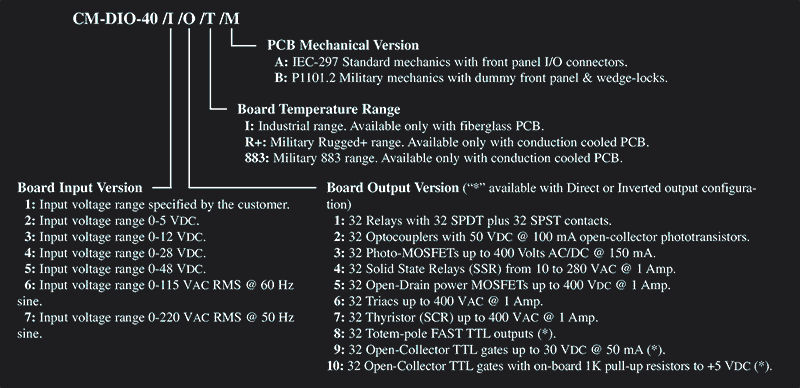
Ordering Example: CM-DIO-40 /I /O /T /M
I (Board Input Version)
1: Input voltage range specified by the customer.
2: Input voltage range 0-5 VDC.
3: Input voltage range 0-12 VDC.
4: Input voltage range 0-28 VDC.
5: Input voltage range 0-48 VDC.
6: Input voltage range 0-115 VAC RMS @ 60 Hz sine.
7: Input voltage range 0-220 VAC RMS @ 50 Hz sine.
8: Input voltage range 0-26 VAC RMS @ 400 Hz sine.
9: Input voltage range 0-32 VAC RMS @ 60 Hz sine.
O (Board Output Version)
NOTE: * available with Direct or Inverted output configuration
1: 32 Relays with 32 SPDT or 32 SPST contacts.
2: 32 Optocouplers with 50 VDC @ 100 mA open-collector photo transistors.
3: 32 Photo-MOSFETs up to 400 Volts AC/DC @ 150 mA.
4: 32 Solid State Relays (SSR) from 10 to 280 VAC @ 1 Amp.
5: 32 Open-Drain power MOSFETs up to 400 VDC @ 1 Amp.
6: 32 Triacs up to 400 VAC @ 1 Amp.
7: 32 Thyristor (SCR) up to 400 VAC @ 1 Amp.
8: 32 Totem-pole FAST TTL outputs *.
9: 32 Open-Collector TTL gates up to 30 VDC @ 50 mA (*).
10: 32 Open-Collector TTL gates, 1K pull-up resistors to +5 VDC *.
11: 32 Open-Collector TTL gates, 2K pull-up resistors to +12 VDC *.
CM-DIO-40
T (Board Temperature Range)
I: Industrial. Fiberglass PCB only.
R+: Military Rugged+. Conduction cooled PCB only.
883: Military 883. Conduction cooled PCB only.
M (PCB Mechanical Version)
A: IEC-297 Mechanics with front panel I/O connectors.
B: P1101.2 Military mechanics with dummy front panel & wedge-locks.
Ordering Example
Part Number Example: CM-DIO-40/2/1/R+/B
- Input voltage range: 0-5 VDC.
- Output version: 32 relays with 32 SPDT contacts.
- Military Rugged+ range (-40 to +85°C operating).
- IEEE P1101.2 Military mechanics with wedge-locks.
Documentation
LEVEL 1, CM-DIO-40 MAP: User´s manual. Module hardware functional description oriented toward software development.
LEVEL 2, CM-DIO-40 MMT: Maintenance manual. Extended description intended for failure location in the module.
Software Support
Wind River Systems VxWorks Tornado: The CM-DIO-40 is supported by VxWorks Tornado. This operating system is ideal for developing real time software under UNIX environments. A complete "C" language driver in source code is available at low cost. Drivers include a floppy-disk and user's manual.
Microtec MCC-68K Drivers: A "C" language source code driver written for the popular MCC-68K cross-compiler from Microtec is also available. This low cost option is intended for using a PC as host.
* NOTE - Drivers for other leading operating systems can be optionally supplied under request.