CM-DI-40
The CM-DI-40 is a general purpose 64 channel optocoupled input VMEbus board, incorporating features most demanded in today's first class military & industrial applications.

The board implements a complete input voltage stage per channel, featuring overvoltage protection, galvanic isolation, rectifier & filter and easy configuration to accept a wide range of AC/DC voltage levels.
VMEbus D/I
The metallic layer within the PCB benefits heat dissipation & uniform component temperatures, thus increasing component longevity & module MTBF.

Incorporating Built-In-Test circuitry for testing all on board TTL chips using wraparound loops which read-back channel status to verify correct module operation.
Military versions with thermal overlay greatly improve capability to withstand shock & vibration.
Discrete Input
The CM-DI-40 offers a highly flexible I/O cabling solution using VME64x connectors on both front panel and P2. Both connectors have identical pin-out.

All versions are compatible at the function level, Industrial versions allow low cost software development.
Commercial

CM-DI-40/C
C: Commercial range >> Implements low cost Commercial plastic IC's rated for 0 to +70°C. Continuous board operation from 0 to +60°C. Class II industrial quality connectors. Storage from -10 to +85°C.
Industrial

CM-DI-40/I
I: Industrial range >> Manufactured with Industrial range plastic or ceramic IC's rated for -25 (-40) to +85°C. Continuous module operation from -20 to +75°C. Class II industrial quality connectors. Storage from -40 to +100°C.
Rugged+

CM-DI-40/R+/A
R+: Military Rugged+ range >> Implements ceramic IC's rated from -55 to +125°C. Class I MIL-C-55302 connectors. Conduction cooled PCB with thermal overlay. Operation from -40 to +85°C. Storage from -55 to +125°C.
Military 883

CM-DI-40/883/B
883: Military 883 range >> Manufactured with conduction cooled PCB & MIL-STD-883 B/C military ceramic parts (-55 to +125°C). Class I MIL-C-55302 connectors. Operation from -50 to +90°C. Storage from -55 to +125°C.
MIL-STD Components
- MIL-STD-810D Temperature (Methods 501.2 & 502.2)
- -55°C to +125°C ceramic military ICs
- Military Class V Printed Circuit Board
- MIL-C-55302 Class I Connectors
- MIL-R-39016 Built-In-Test Relays.
- MIL-STD-883 FPGAs & TTL chips.
- MIL-E-5400 Class 1B (Temp. & Altitude)
- MIL-STD-810D Shock & Vibration (Methods 514 & 516)
- No PCB tracks in external layers
- MIL-STD-810D Saline Fog & Dust (Methods 507 & 509)
CM-DI-40 Specifications
- Input channels: 64 independent floating channels each one fitted with optocoupler.
- Input overvoltage: Up to 30% nominal for extended periods. 300% for transitory peaks.
- Galvanic isolation: Full galvanic isolation >1000V on all channels with respect to the VMEbus power & TTL lines.
- Input voltage ranges: Can be factory fitted for any range from 3 to 300 VAC/DC.
- Input Change Detector: Programmable input sampling rate from 122Hz to 62.5KHz.
- Channel protection: 1 W resistor & 1 W zener diode.
- Input current (ON): 3 to 5 mA per channel.
- Control Register: Manages BIT and enables IRQs.
- Front panel LEDs: 64 LEDs. Illuminated when associated channel is driven by nominal voltage (ON).
- Optocoupler frequency: DC to 10KHz.
- Power consumption: +5VDC @ 450mA.
- Board Weight: Military R+ & 883.- 565 grams. Industrial.- 430 grams.
- Mechanical size: Single slot 6U (233.4x160 mm).
- VMEbus Interface: A24/D16 Standard slave interface.
- VMEbus Interrupter: I(1-7). Asserts IRQs to the VME master on channel input changes.
- VMEbus addressing: Two jumper blocks provide 256 mapping options in the A24 range.
- Mechanical format:
- CM-DI-40/A: IEC-297 mechanics for 19 inch racks with I/O on front panel.
- CM-DI-40/B: Military IEEE P1101 wedgelock mechanics for ATR enclosures.
- Humidity: Up to 95% RH non-condensing.
- Altitude: Sea level up to 15 Km (50,000 ft.).
CM-DI-40 Features
- 64 discrete input channels per board.
- 3 to 300 VRMS AC/DC input range.
- Full galvanic isolation >1000 V per channel.
- Input Change Detector samples and compares all input channels and asserts interrupts on any change. I (1-7) VMEbus Interrupter.
- Overvoltage input protection per channel.
- Discrete input signals via 160 pin VME64x connectors on front panel and P2.
- 64 LED indicators on front panel show all output channels ON-OFF status.
- Low power CMOS design (3 watts).
- On board Built-In-Test capability allows testing all module TTL chips.
- Industrial, MIL-Rugged & MIL-STD-883 versions.
- Available in IEC-297 mechanics, I/O via front panel & military P1101.2 mechanics with wedge-locks.
- Conduction cooled PCB with thermal overlay in MIL-Rugged and 883 versions.
- Extensive software support.
- Extremely simple programming.
- Excellent price/performance ratio.
- Two year guarantee.
CM-DI-40 Ordering
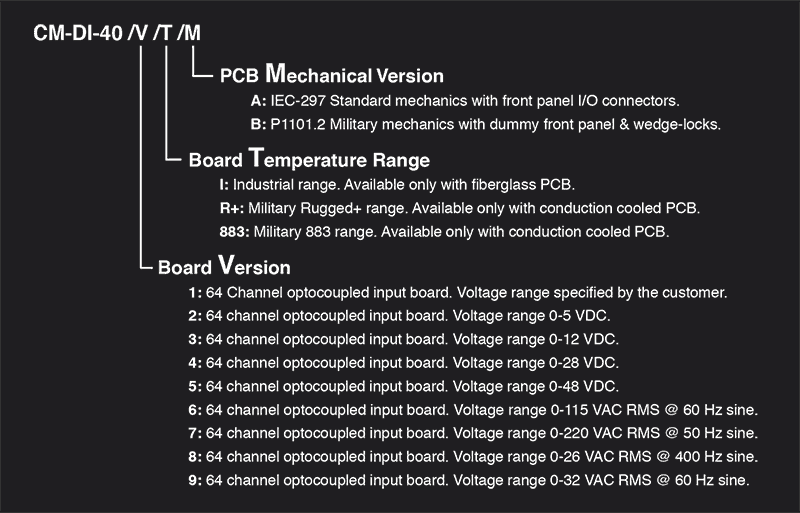
Ordering Example: CM-DI-40 /V /T /M
V (Board Version)
1: 64 Channel optocoupled input board. Voltage range specified by the customer.
2: 64 channel optocoupled input board. Voltage range 0-5 VDC.
3: 64 channel optocoupled input board. Voltage range 0-12 VDC.
4: 64 channel optocoupled input board. Voltage range 0-28 VDC.
5: 64 channel optocoupled input board. Voltage range 0-48 VDC.
6: 64 channel optocoupled input board. Voltage range 0-115 VAC RMS @ 60 Hz sine.
7: 64 channel optocoupled input board. Voltage range 0-220 VAC RMS @ 50 Hz sine.
8: 64 channel optocoupled input board. Voltage range 0-26 VAC RMS @ 400 Hz sine.
9: 64 channel optocoupled input board. Voltage range 0-32 VAC RMS @ 60 Hz sine.
T (Board Temperature Range)
I: Industrial. Fiberglass PCB only.
R+: Military Rugged+. Conduction cooled PCB only.
883: Military 883. Conduction cooled PCB only.
VMEbus DI-40
M (PCB Mechanical Version)
A: IEC-297 Mechanics with front panel I/O connectors.
B: P1101.2 Military mechanics, dummy front panel & wedge-locks.
Ordering Example
Part Number Example: CM-DI-40/2/R+/B
- 64 Channel optocoupled input board. Voltage range 0-5 VDC.
- Military Rugged+ range (-40 to +85°C operating).
- IEEE P1101.2 Military mechanics with wedge-locks.
Documentation
LEVEL 1, CM-DI-40 MAP: User´s manual. Module hardware functional description oriented toward software development.
LEVEL 2, CM-DI-40 MMT: Maintenance manual. Extended description intended for failure location in the module.
Software Support
Wind River Systems VxWorks Tornado: The CM-DI-40 is supported by VxWorks Tornado & is ideal for developing real time software under UNIX environments. A complete "C" language driver in source code is available at low cost. Drivers include a floppy-disk & user's manual.
Microware Systems OS-9: Drivers for the real time OS-9 Operating System are available in "C" language. This driver is supplied with user's manual & source code floppy-disk.
Microtec Research MCC-68K Drivers: A "C" language source code driver written for the MCC-68K cross-compiler from Microtec Research. This low cost option is intended for using a PC as host.
* NOTE - Drivers for other leading operating systems can be optionally supplied under request.